Oh man there were a lot of numbers to think about today… Subconciously, I knew that it would be very hard to figure out how big everything should be. There are also things in the project such as spacing between LEDS and the size of the bolts I have that cannot be easily changed. This means I am constrained in some ways with what I can do.
I started out thinking I would build a 200 x 200 x 30 mm box.
One of my main sources of inspiration for measurements and construction is the Hexagonal Nanoleaf - Hexaleaf project on Thingiverse:
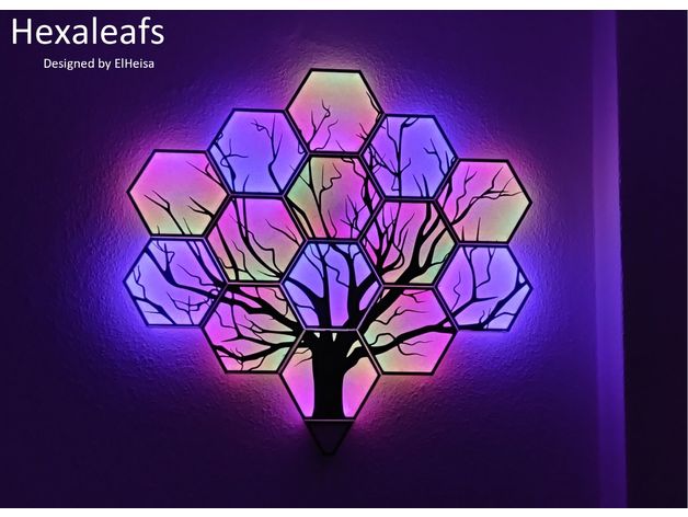
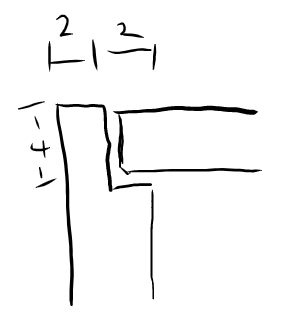
The main difference is I will be making a single, square box instead of multiple hexagons. The creator of Hexaleaf has included some of the dimensions of the project which have been very useful for my own designs:
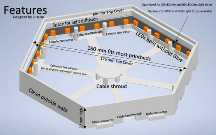
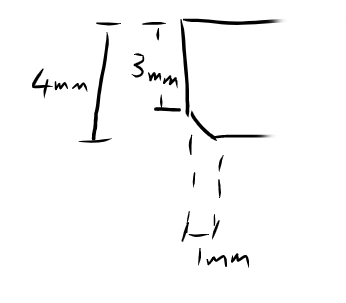
The most important things I got from the above dimensions are the wall width of the enclosure (4 mm), the border width of the cover image (4 mm), and the height of the cover image (4 mm [3 mm + 1 mm sloped section]).:
I was interested to see that Hexaleaf’s depend on friction to hold the cover image in place, like so:
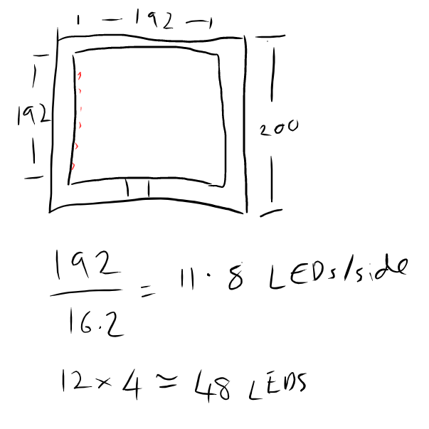
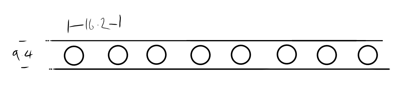
Based on the original 200 x 200 mm dimensions I was targeting, and the 4 mm wall width of the Hexaleafs, I calculated the length of each internal wall to be 192 mm. Given the LEDs I have are spaced 16.2 mm apart, this means I can have approximately 12 LEDs per wall. This would equate to 48 LEDs in total, which I am not sure the Pico can drive.
|
|
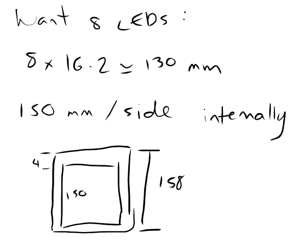
To be on the safe side, I will aim for 30 LEDs maximumm, 8 on the left, top, and right walls, and 6 on the bottom wall, to account for where the Pico will be mounted.
With this in mind, the ideal internal wall length will be more like 130 mm. I will include 10 mm on either side, giving a final internal wall length of 150 mm. Including the 4 mm wall width, results in a 158 x 158 mm square:
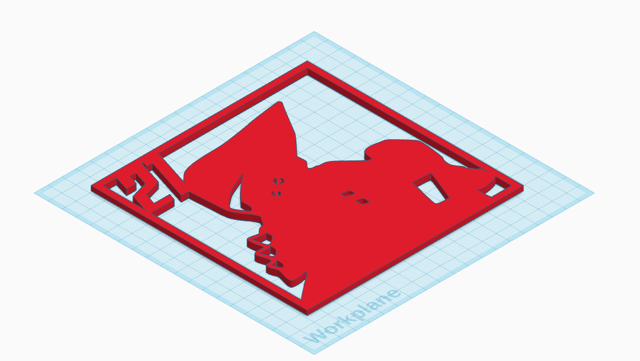
What all of this ends up meaning for the cover image is that it will be 154 x 154 mm:
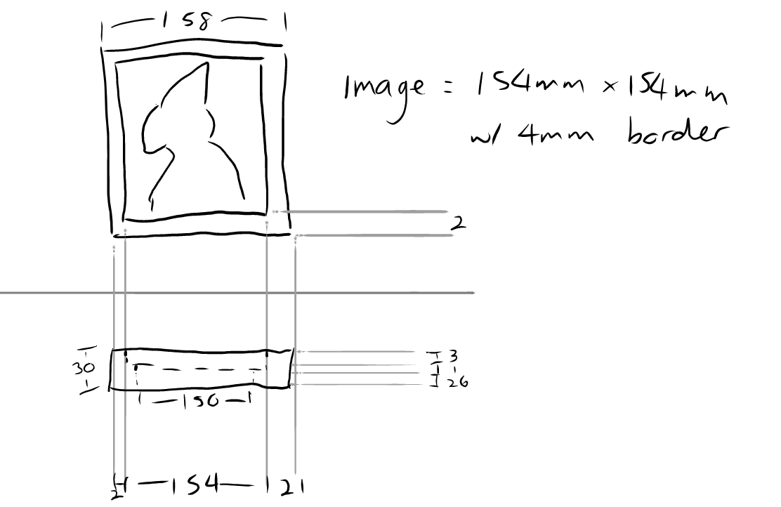
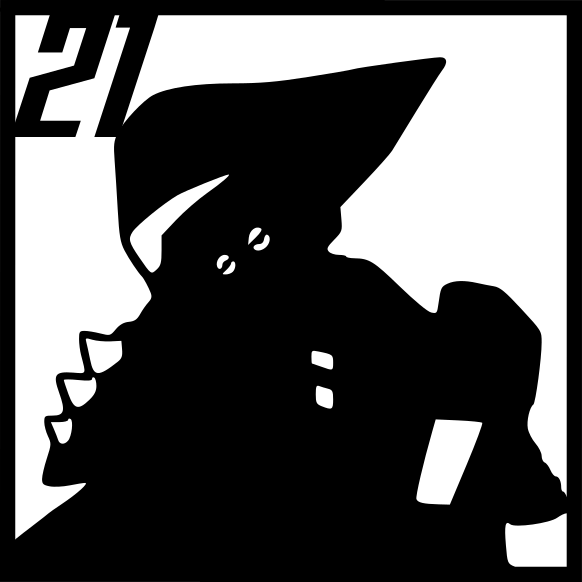
I ended up having to tweak the SVG a bit to make sure the border is 4 mm:
That was just for the X and Y axis of the project… Let’s talk about the Z axis 😅.
There are several layers to the Z axis:
- Cover image
- LED strip
- Base of the enclosure
There is also the Rasperry Pi Pico but that will sit in the middle of the enclosure and it not very thick so don’t think it needs to be included here. I will add a 1 mm space between the LED strip and top/bottom of the enclosure.
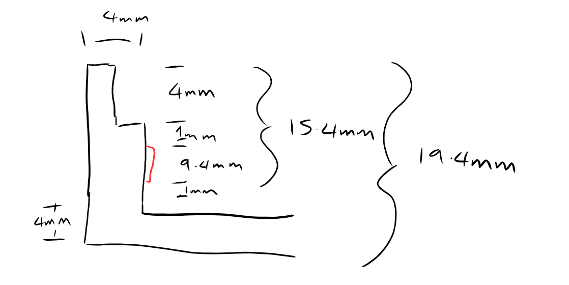
Given the above:
4 mm (cover image) + 1 mm + 9.4 mm (LED strip) + 1 mm + 4 mm (base) = 19.4 mm
Tinkercad
I had a go at getting the SVG into Tinkercad. It was a bit of a battle because Tinkercad doesn’t seem to deal with anything except paths (i.e. text and shapes don’t work). Happy with the result: