I was happy with the spray paint test I did the other day but obviously when it comes to doing the real thing, the pressure is on!
From what I have read about post-processing 3D prints, it is a good idea to suspend the print in the air from a piece of string or similar. You then apply even strokes of paint while rotating the print. I used some thin string and tied it to the cover and enclosure.
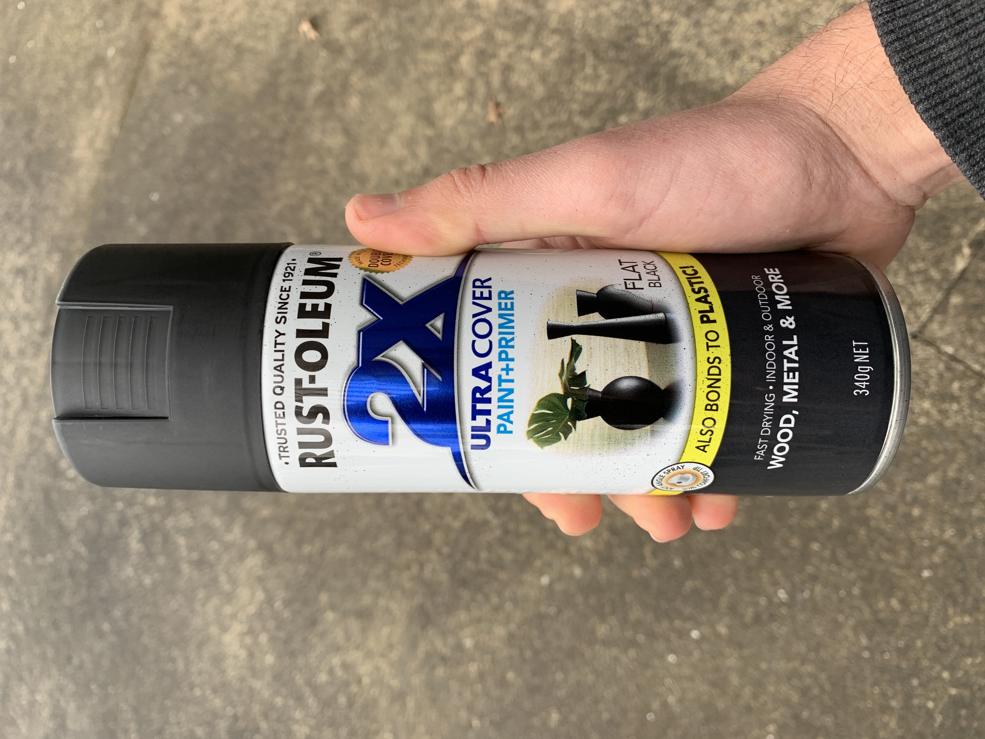
The spray paint I am using is Flat Black Rust-oleum:
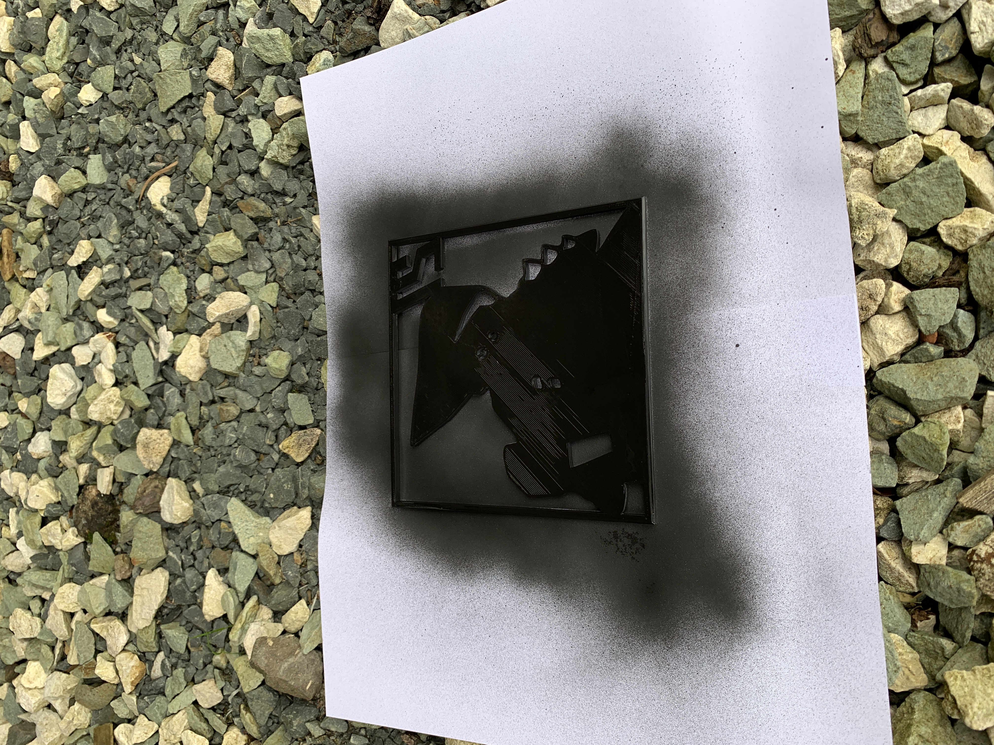
I started with the enclosure and tried to apply nice even strokes. I could tell pretty quickly that hanging the piece vertically was not the best idea. A drip-like pattern was appearing on the back of the enclosure as gravity caused the paint to move. From then on, I decided to just lay the pieces flat and spray on top of some paper. When dry, I would turn the piece over and spray the other side. I did two coats of paint per side:
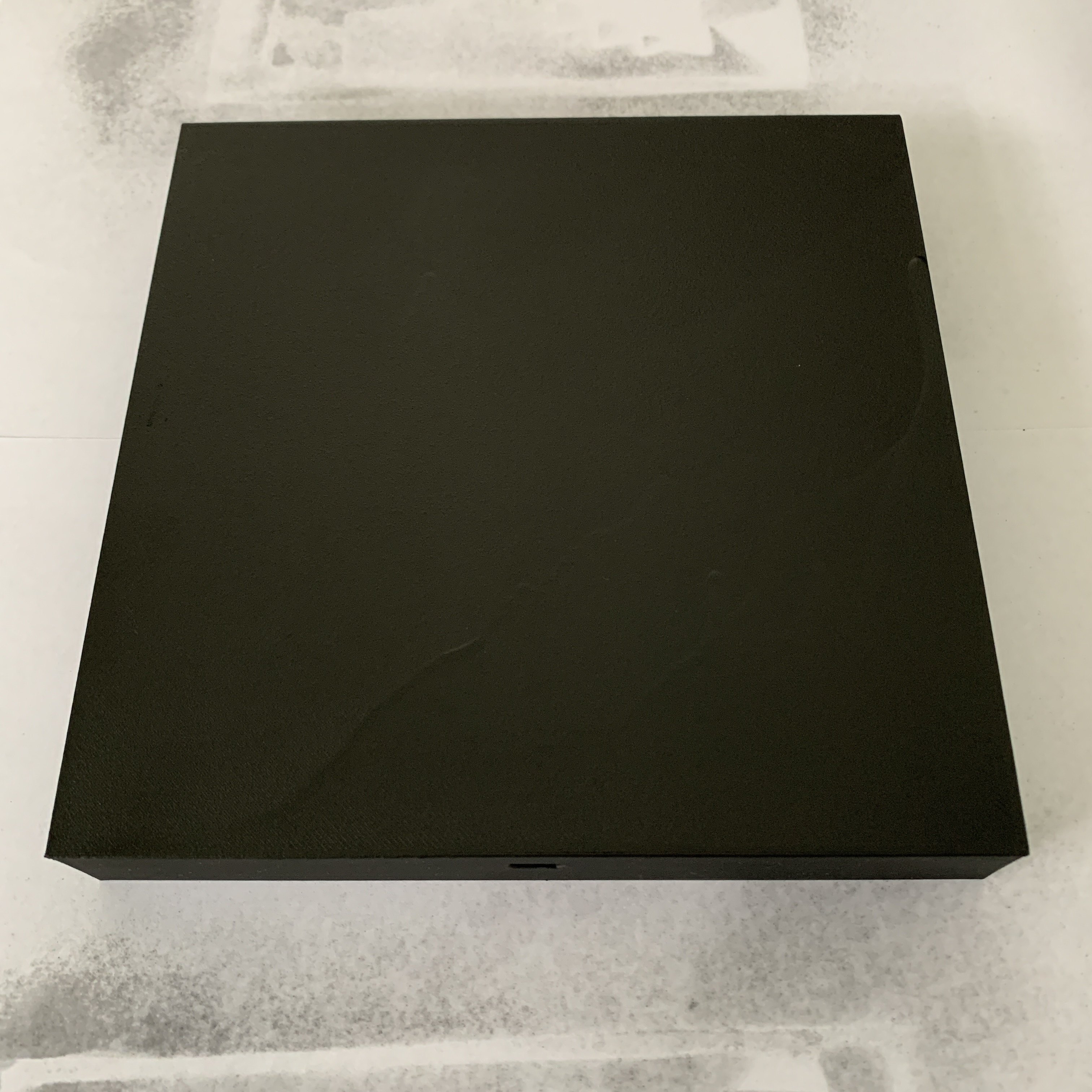
I will leave both pieces to dry for 24 hours before trying to fit them together.
Soldering the Wires to the Pico
I initially wanted to avoid soldering anything to the Pico itself because that is semi-permanent. My preference was to use wires with female headers on one end and plug them into the header pins on the Pico. Unfortunately, that increases the height of the Pico a lot, and I would have to make the enclosure a lot thicker to accommodate for this. My goal was to make the project as thin as possible so I decided to solder the three required wires directly to the Pico. As you can see, this adds no height and is far easier to fit into a thin space:
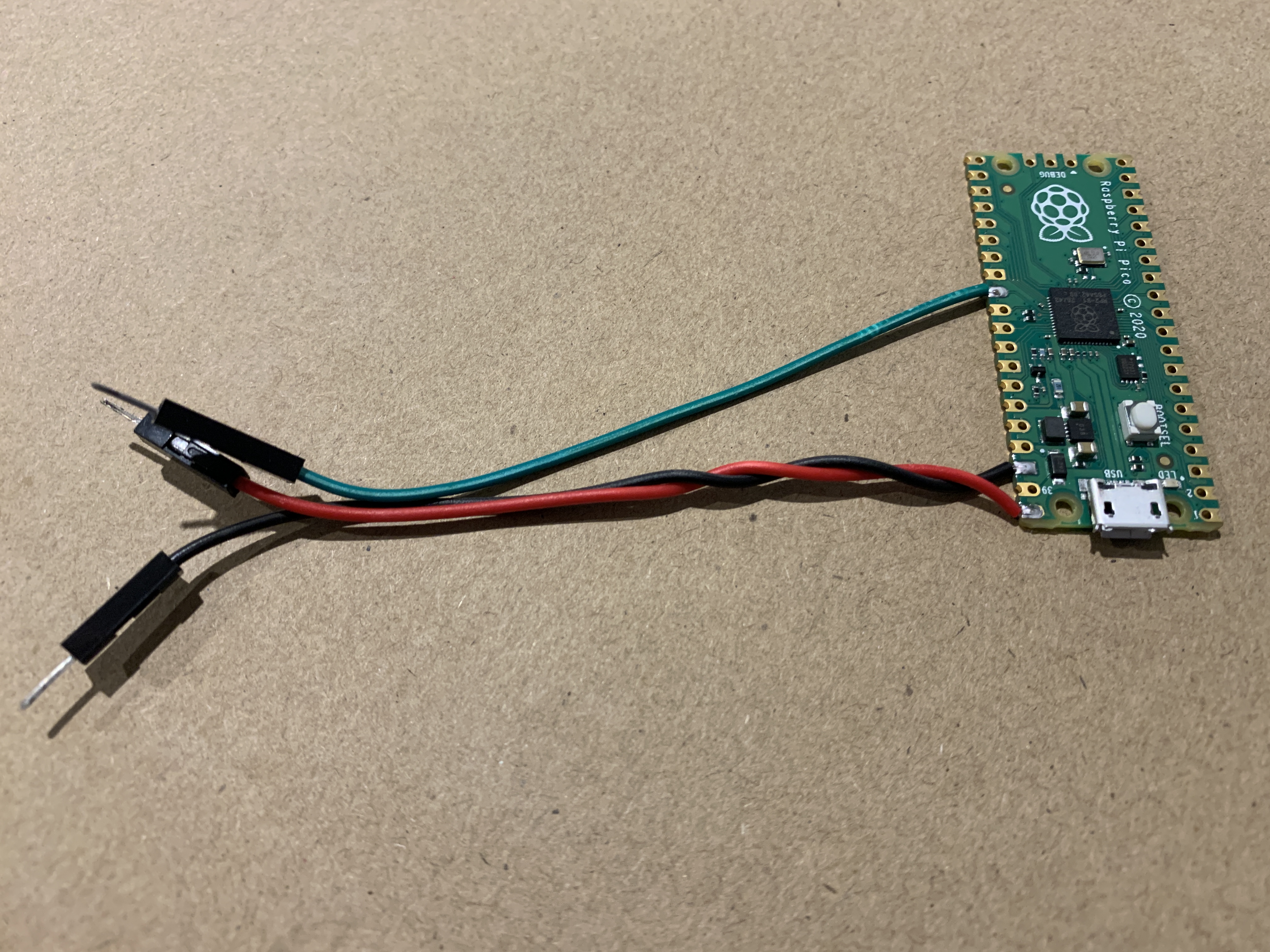
The data wire (green) was originally set to the bottom right pin shown in the picture above (GP0):
pixels = neopixel.NeoPixel(board.GP0, num_pixels, auto_write=False)If I kept using the bottom right pin, I would have had to bend it over/under the Pico to be on the same side as the red (VBUS) and black (GND) wires. Instead, I decided to use a GPIO pin on the left side of the board, as close to the other wires as possible. GP22 seemed like a good candidate so I changed the wiring and updated the code to the following:
pixels = neopixel.NeoPixel(board.GP22, num_pixels, auto_write=False)The LED strip turned on as expected 💡.