Today is the day I am nervous about. The enclosure is the longest and highest thing I have printed so I am really hopeful it goes well.
I started it as early as I could so it will be done by early evening. That will give me enough time to examine, clean and test everything fits.
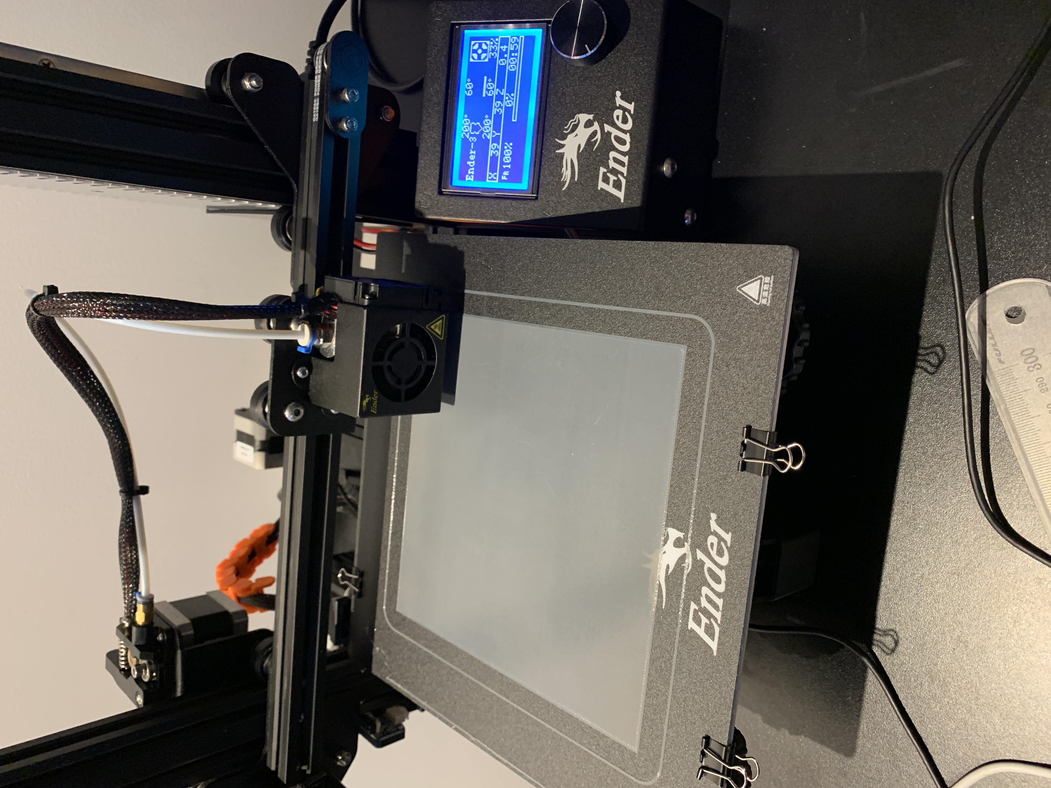
Here we go…
It took an hour just to print the first layer 😲.
I will often look at the GCode viewer in Octoprint because I find it interesting. I noticed early on in the print that the print time left was 3 days:
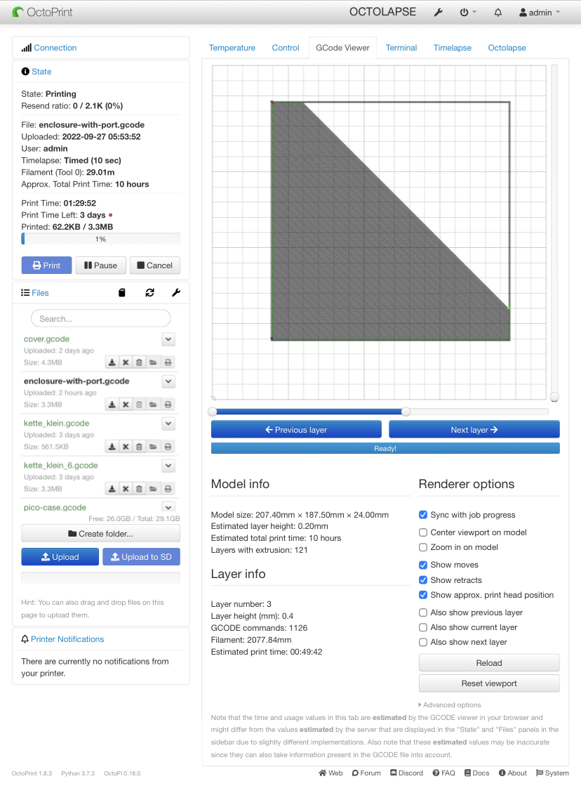
Reminds me of this 🤣.

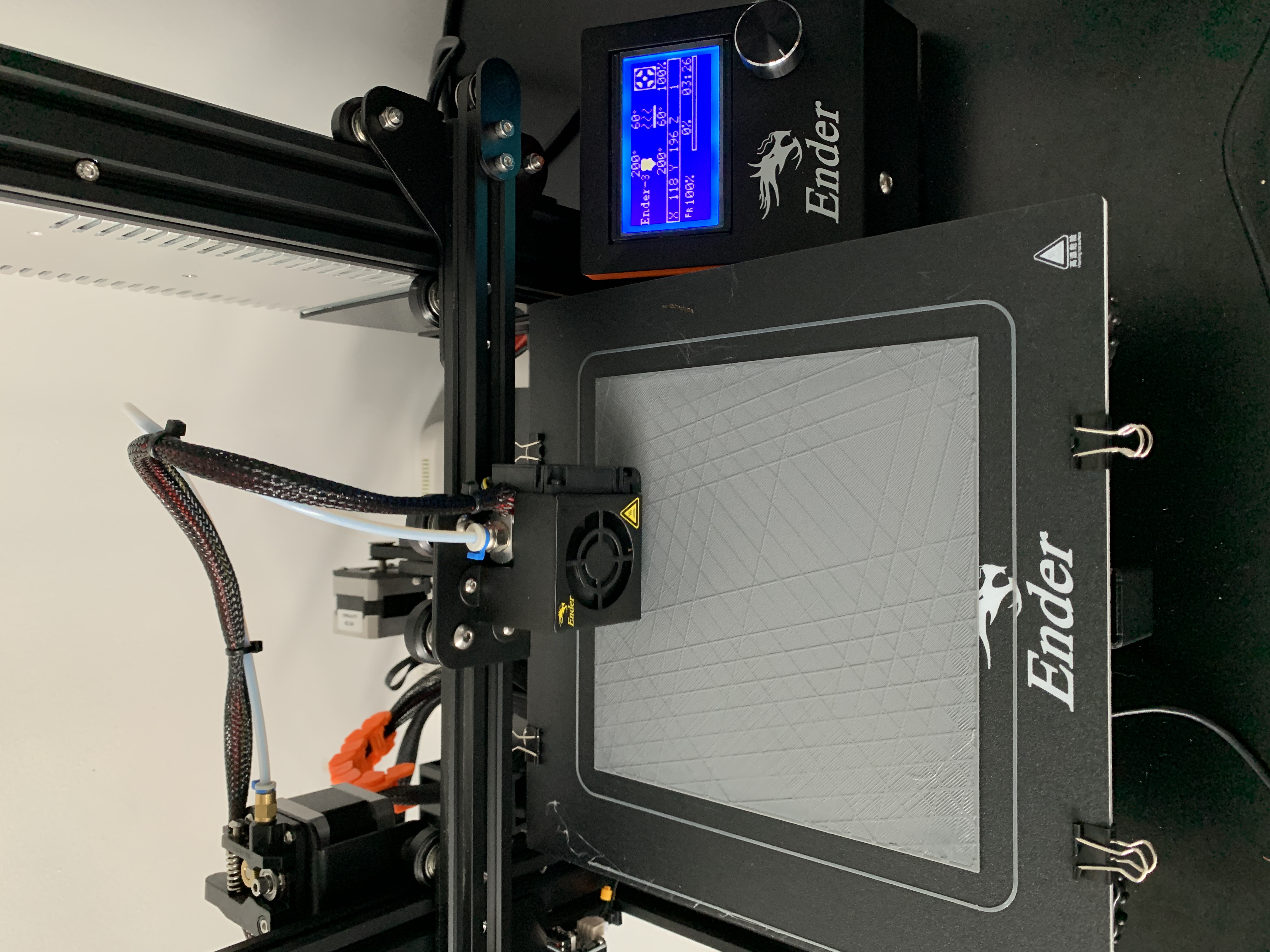
At the 3 and a half hour mark, the infill pattern emerged:
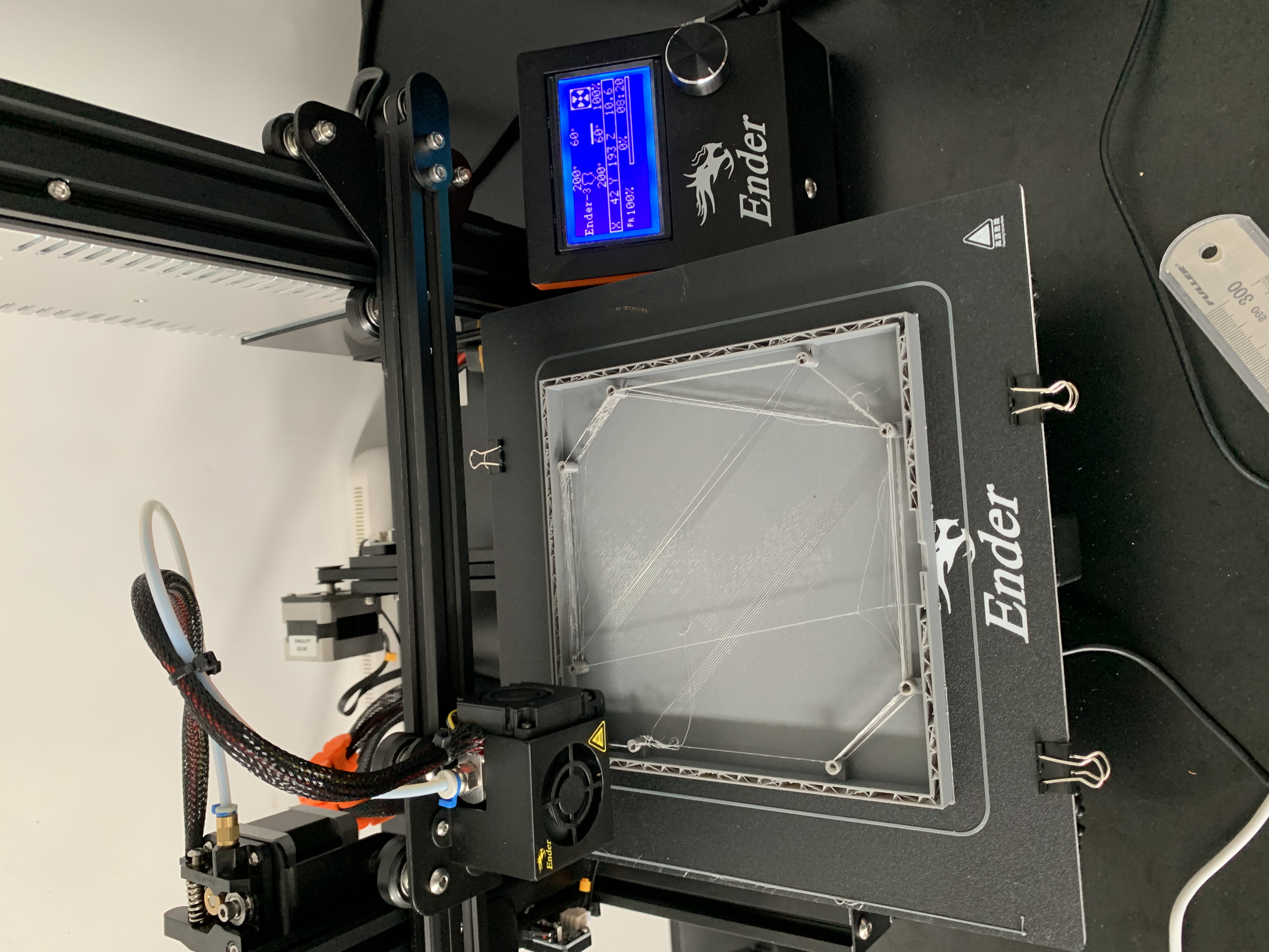
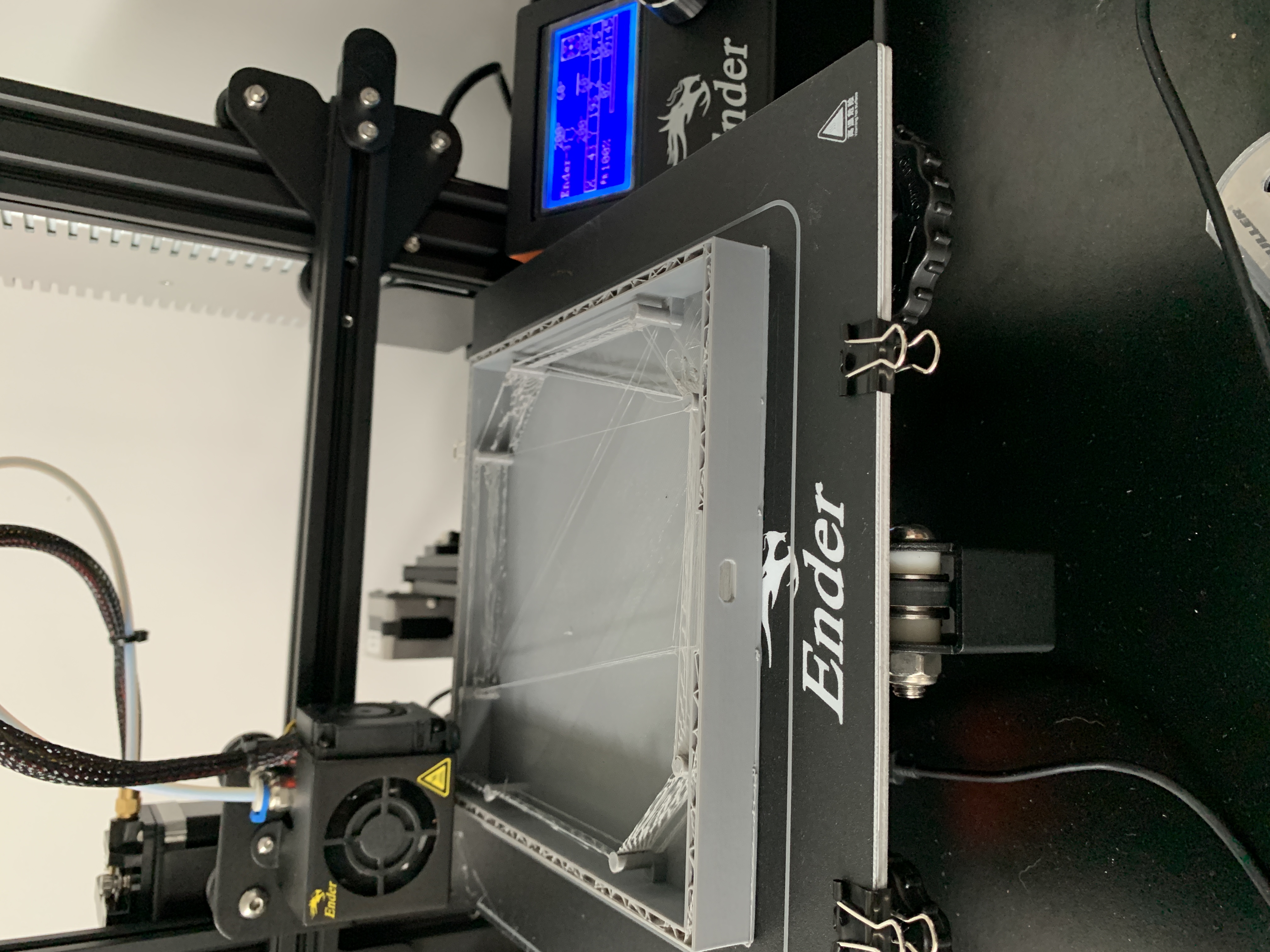
Once the cylindrical holders for the LED strip started printing, I started seeing some mean stringing. I was not too concerned because this can be tidied up when the print is finished. I did keep a close eye on it though to make sure the strings would not obstruct the print nozzle:
Eventually, I could see the micro USB port appearing. I then came to a realisation that I had not accounted for the print overhang for the top of the port. You can obviously not print onto thin air so I began to plan how to handle this when the print reached that layer. I decided to just observe the first pass of filament over the port gap. To my surprise, the filament remained suspended and did not sag at all. I left the next couple of layers to print without any intervention from me. Turns out I was worried for nothing 🥹.
Again, I managed to get a screenshot of the Gcode viewer just before the print completed:
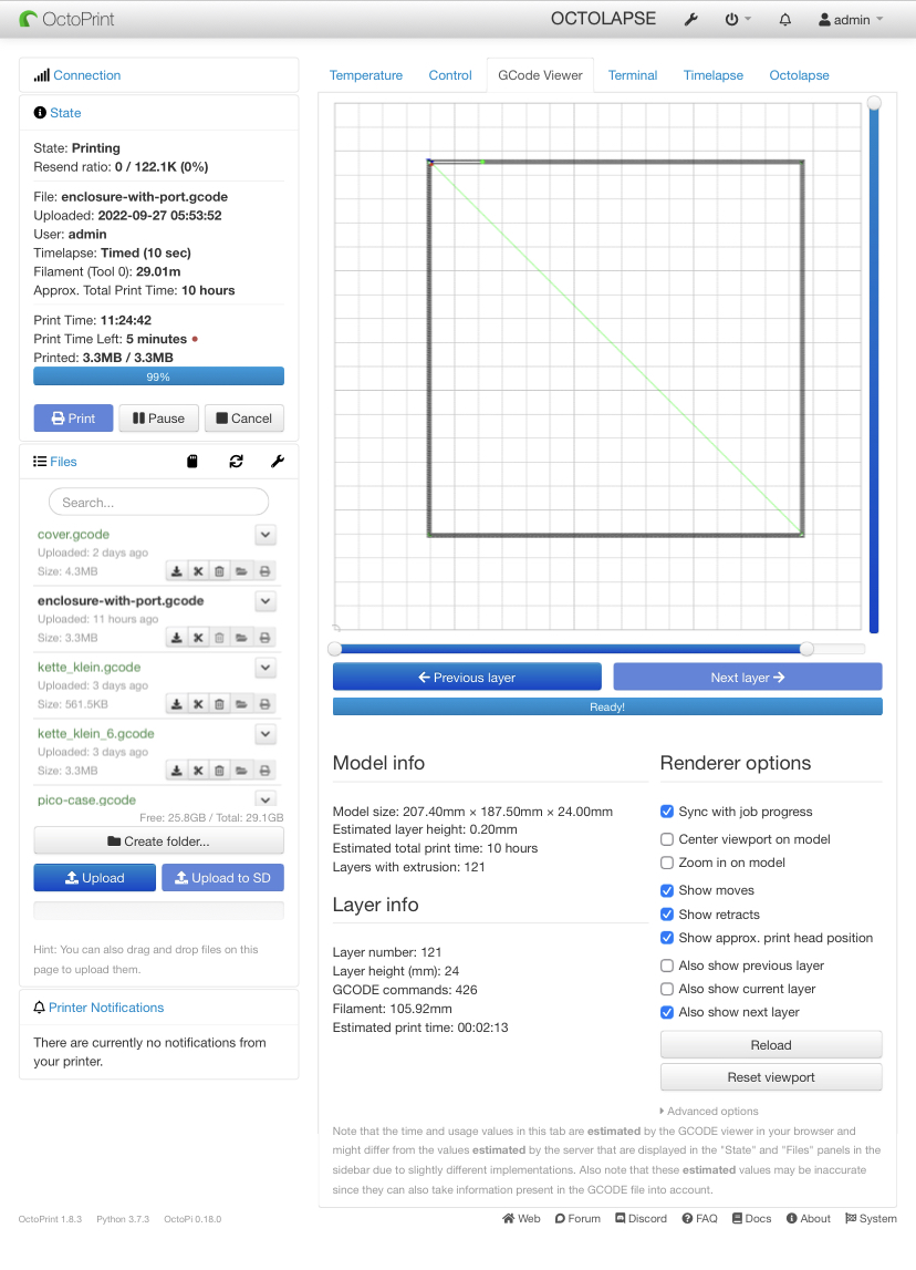
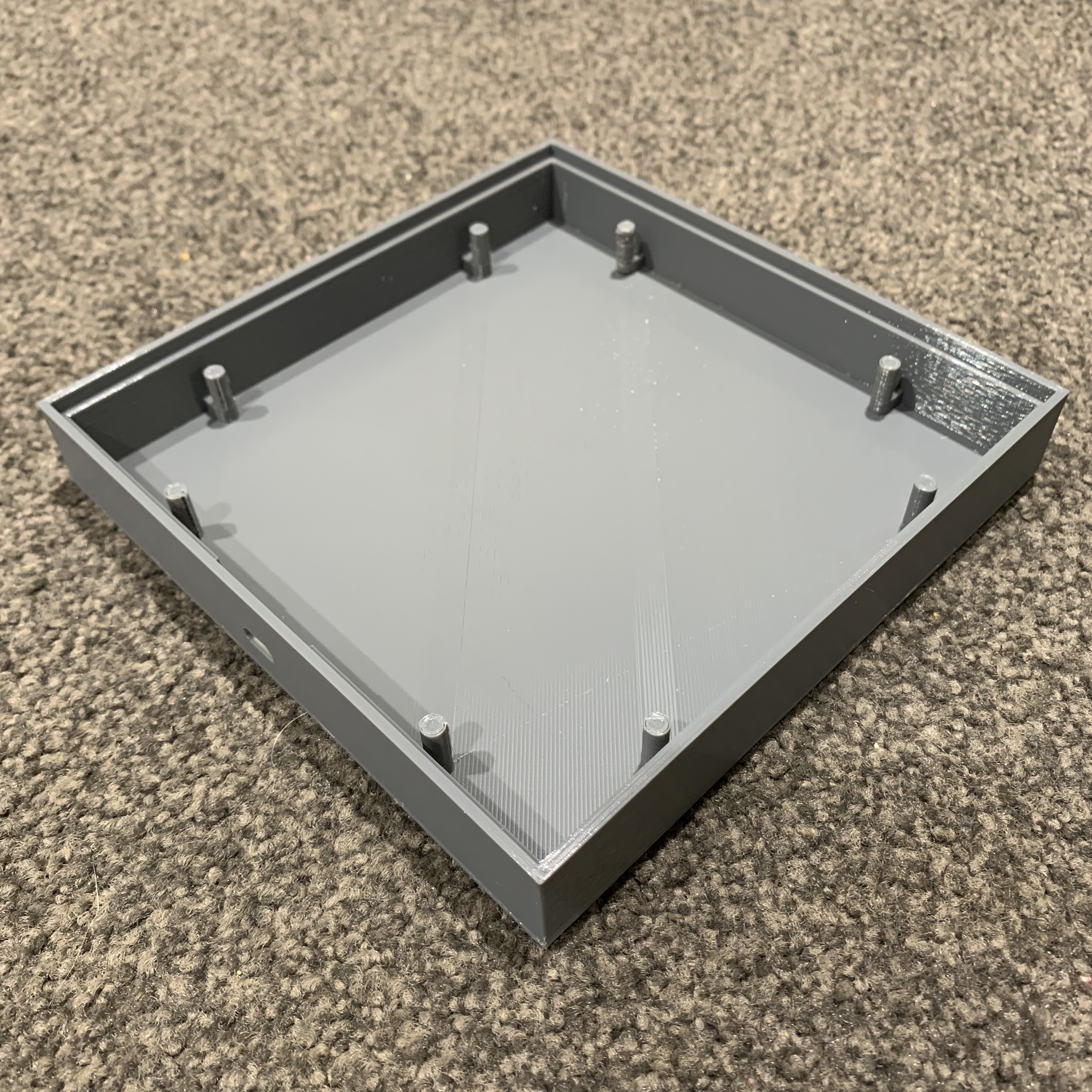
After 11 hours 24 minutes and 29.01 m of filament, the enclosure was done!
One of the first things I did was to check if the Raspberry Pi Pico case I printed the other day fits with the port I designed on the enclosure. I realised quite quickly I had made a mistake. The person who designed the Pico case did a great job. The issue is I made the port in the enclosure the same dimensions as the one in the case. That port is not designed for a micro USB cable to pass through, but rather for the connector to plug in perfectly. You can see that clearly in this photo:
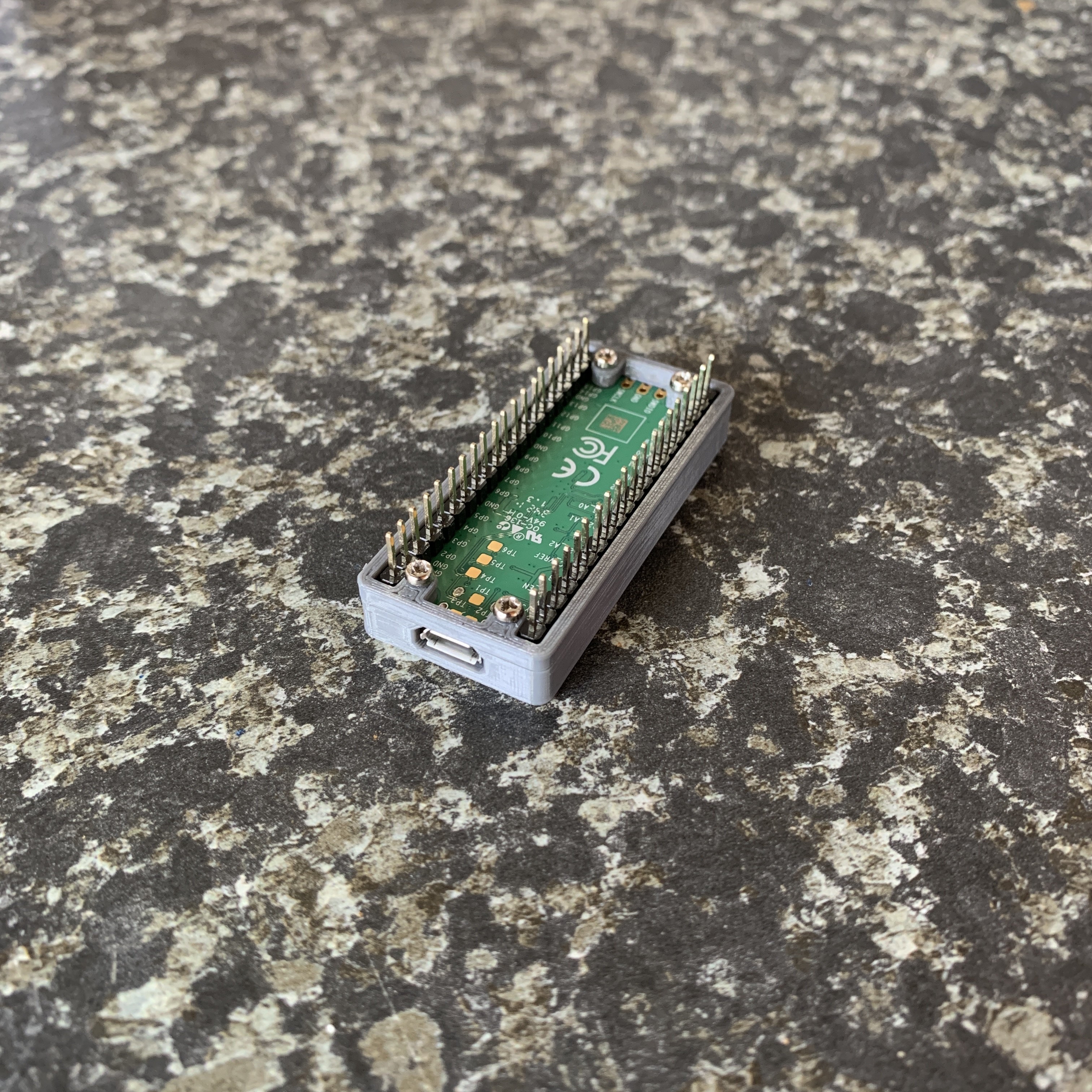
The cable plugs in nicely, but there is no clearance for the rest of the cable. Therefore, there is no way for me to plug in a cable from the outside of the enclosure. I started thinking about how to make the hole in the enclosure bigger (soldering iron, sandpaper, Drememl, etc.), but then I realised it would easier to remix the Pico case design. The goal is to remove the side of the case the port is on, so the case and Pico will sit flush with the inside of the enclosure. That should allow the Pico to be accessible from the outside.
This is the design I came up with:
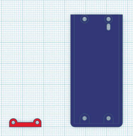
The blue part is the original case bottom with the wall with the port removed. I will print two of the red part to hold the Pico in place with screws.
Clean Up and Fit Test
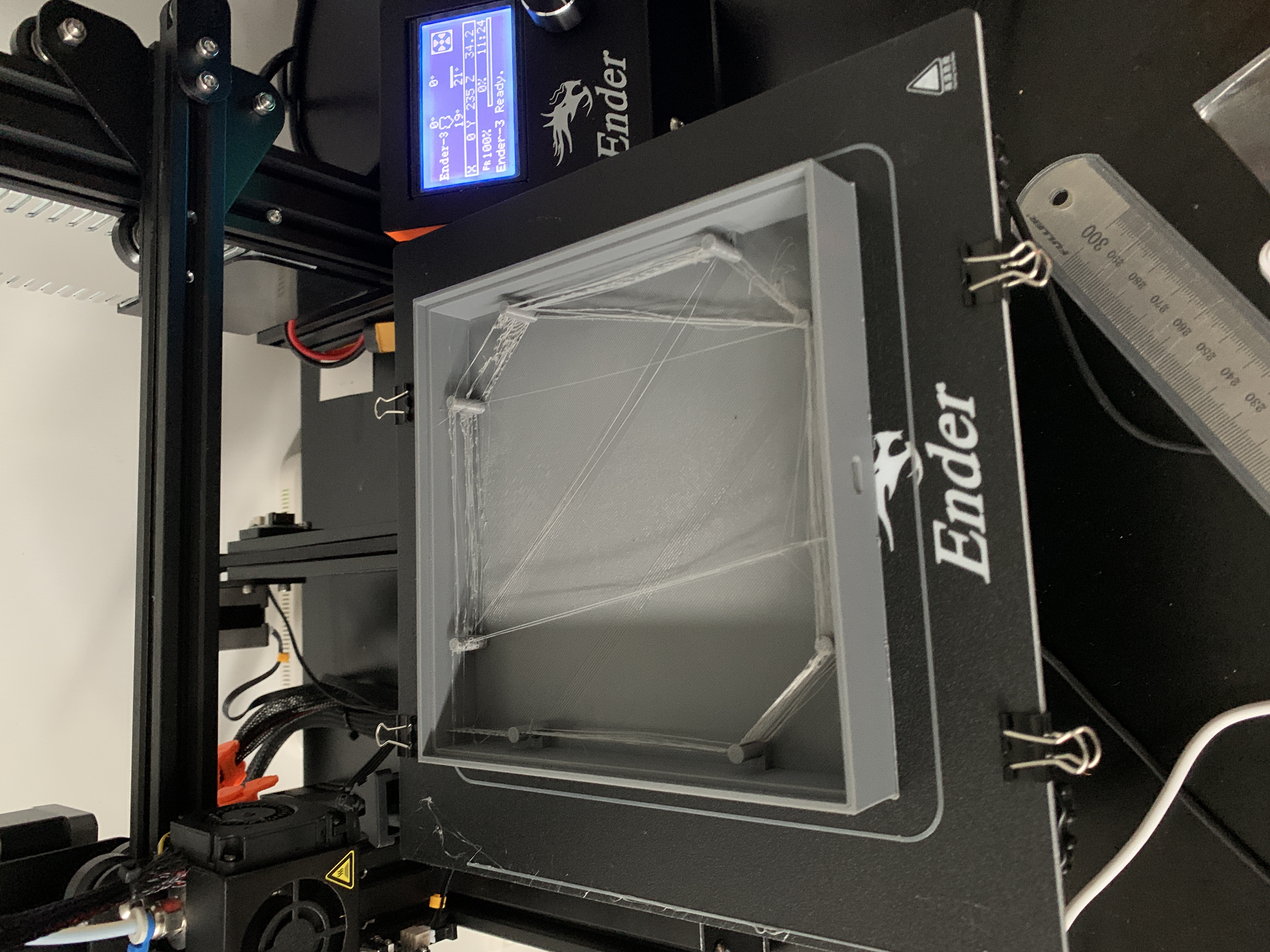
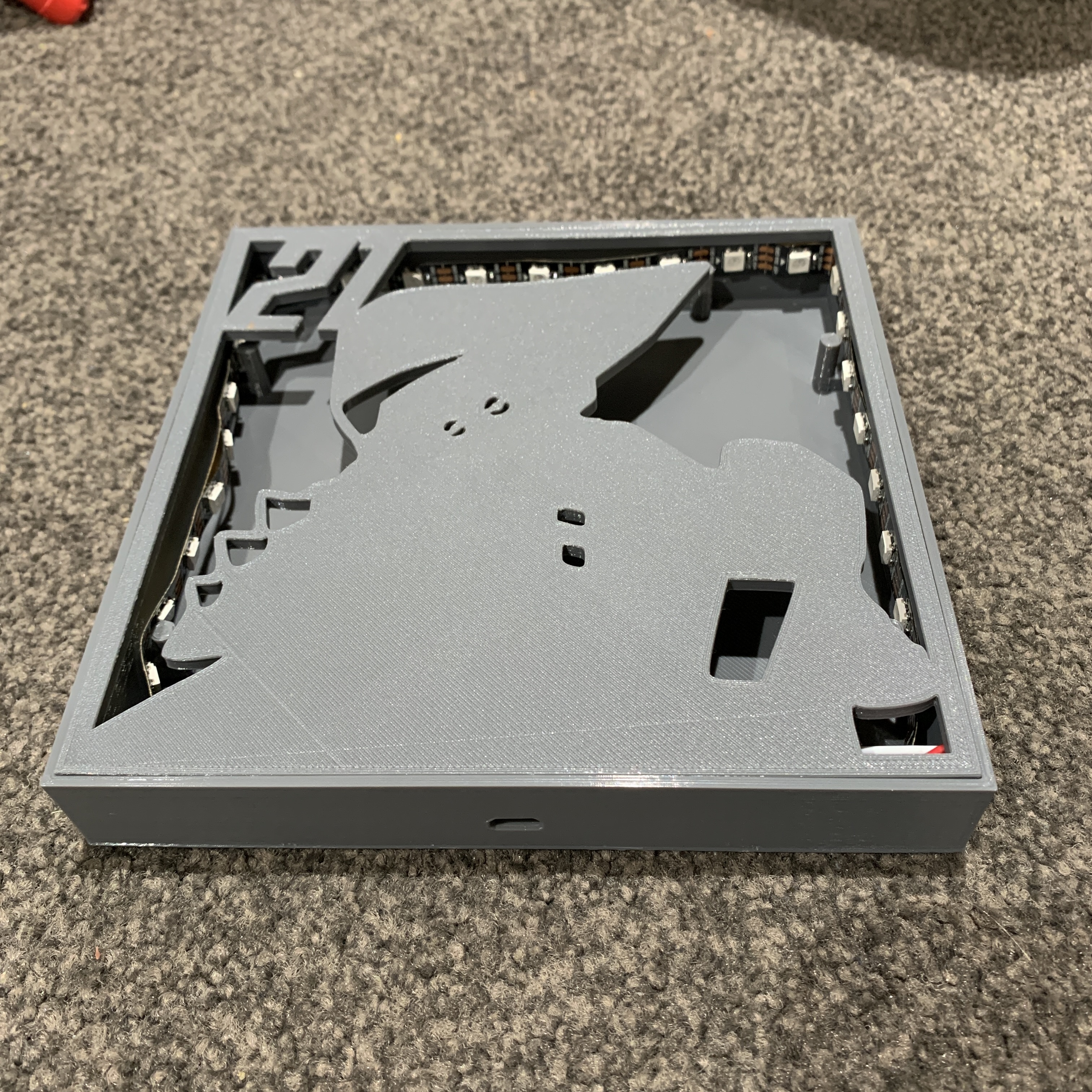
Time to move on to tidying up the enclosure and checking to see if the cover fits… After carefully cutting away the stringed sections, and the imperfections on the outside of the enclosure, this was the result:
Now for the moment of truth, fitting the cover into the enclosure:
Woohoo! 🥳 I am really pleased with how the cover fits. It is pretty snug but I am not confident it would hold in place for a long time. I wonder if the spray paint will add any thickness and make the fit any more snug. I will have to test this.